Main structural configuration:
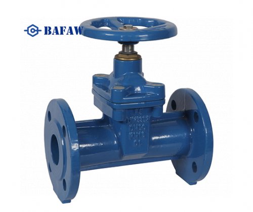
This valve consists of a valve body, rubber sleeve, large and small valve stems, pressure plates, pull rods, brackets, handwheels, and other components.
Working principle:
When the handwheel is turned clockwise, the large and small valve stems rotate simultaneously to drive the upper and lower pressure plates, compressing the rubber sleeve to close the valve. Conversely, turning the handwheel counterclockwise opens the valve. The pressure plates move up and down between the pull rods to complete the valve opening and closing operation.
Notes:
Since the rubber sleeve has low load-bearing capacity, when opening or closing the valve, the operator should stop rotating the handwheel once a moderate resistance is felt, indicating the valve has reached its opening or closing limit. Do not force the valve or use multiple people to assist, and do not use other tools to open or close the valve.
Installation and Maintenance:
① This valve can be installed in any position on the pipeline and has no restrictions on the direction of medium flow.
② This valve has low maintenance costs, with no need for regular replacement of valve seats, seal packing, seals, or expansion tubes. The rubber hose is the only part that needs to be replaced in the clamp valve. Once the rubber hose is replaced, the valve functions like a new one. This valve rarely requires additional parts inventory.
Main Performance Specifications
Operating Temperature | Operating Medium |
≤85°C | Slurry, abrasives, dry and wet dust types |
Main Component Materials
Name | Material |
Valve Body | Aluminum alloy, cast iron, cast steel |
Rubber Sleeve | Rubber |
Large Valve Stem | Cast copper, carbon steel |
Clamping Plate | Ductile iron, cast iron |
Rod | Cast iron, 20# |
Bracket | Ductile iron |
Handwheel | Cast iron |
Main external dimensions
Nominal diameter (DN) | Nominal pressure (MPa) | Working pressure (MPa) | L | L1 | Lo | ΦD | ΦD1 | ΦDo | H | Z-Φ | Weight (kg) |
25 | 0.6 | 0.6 | 145 | 124 | 43 | 115 | 85 | 120 | 150 | 4-Φ14 | 3 |
32 | 160 | 145 | 48 | 135 | 100 | 120 | 174 | 4-Φ18 | 4.5 | ||
40 | 180 | 157 | 59 | 145 | 110 | 120 | 186 | 4-Φ18 | 5.5 | ||
50 | 210 | 160 | 69 | 160 | 125 | 140 | 205 | 4-Φ18 | 7.5 | ||
65 | 250 | 199 | 87 | 180 | 145 | 160 | 238 | 4-Φ18 | 9.0 | ||
80 | 302 | 222 | 102 | 195 | 160 | 180 | 241 | 4-Φ18 | 13.5 | ||
100 | 350 | 250 | 119 | 215 | 180 | 200 | 301 | 8-Φ18 | 20 | ||
125 | 32 | 318 | 145 | 245 | 210 | 240 | 360 | 8-Φ18 | 27.5 | ||
150 | 498 | 350 | 171 | 280 | 240 | 280 | 405 | 8-Φ23 | 43 | ||
200 | 0.4 | 0.4 | 650 | 446 | 235 | 335 | 295 | 400 | 545 | 8-Φ23 | 85 |
250 | 797 | 514 | 278 | 390 | 350 | 450 | 632 | 12-Φ23 | 138 | ||
300 | 935 | 562 | 322 | 440 | 400 | 500 | 741 | 12-Φ23 | 195 | ||
350 | 840 | 790 | 402 | 500 | 460 | 500 | 950 | 16-Φ23 | |||
400 | 910 | 840 | 428 | 565 | 510 | 500 | 980 | 16-Φ26 | |||
Standards adopted Design and construction/structural length: Q/LK00-2018 Flange connection dimensions: JB/T 79-2015 (1.0MPa) |